Pin and Socket Specifications for Parts Used in Insight Products
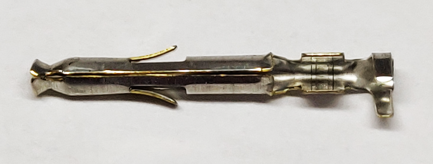
Twin Leaf Pin
| |
|---|---|
| Insight PN | 583616-2 |
| Digikey PN | 583616-2-ND |
| TYCO PN | 5-583616-2 |
| Used In | P1 Edge Connector EGT/CHT/TIT Harness, Carburetor temperature; G1 Only |
| Construction | Gold/Phosphor Bronze |
| Wire Size | 24-28 AWG |
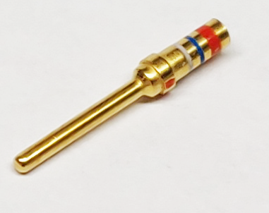
Connector Pin
 |
|
|---|---|
| Insight PN | 205089-1 |
| Digikey PN | A2160-ND |
| Used In | Strikefinder Kit, TAS Install Kit, OAT, Oil Pressure, Oil Temp, Vibration, Fuel Flow, RPM, Signal Junction Box, Combiner Subtractor, Tach Signal Adapter harnesses, Carburetor Temperature, G2, G3, G4 single, G4 twin, G9 |
| Construction | Gold/Phosphor Bronze |
| Wire Size | 20-24 AWG |
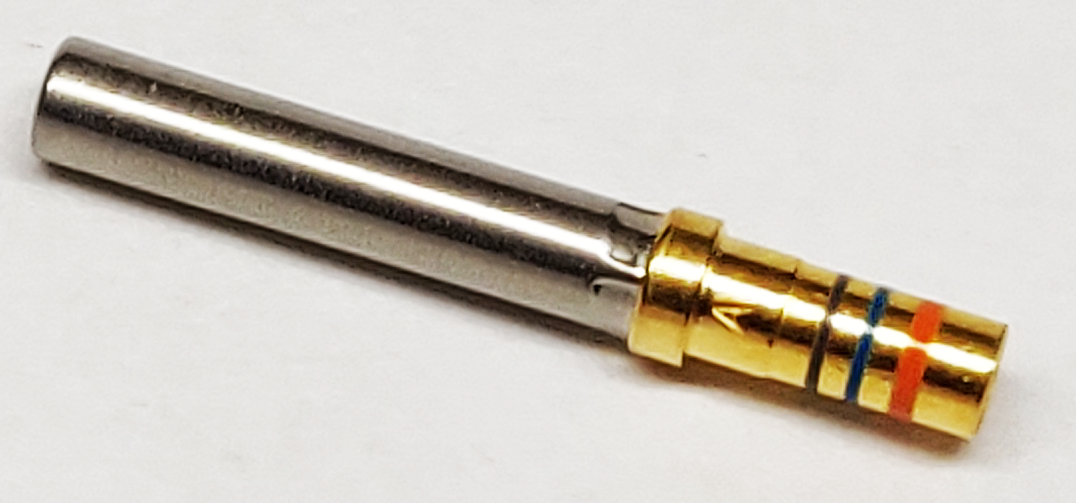
Crimp Socket
 |
|
|---|---|
| Insight PN | 205090-1 |
| Digikey PN | A2161-ND |
| TYCO PN | 205090-1 |
| Used In | Fuel Flow Signal Adapters (all) |
| Construction | Gold Plated |
| Wire Size | 20-24 AWG |
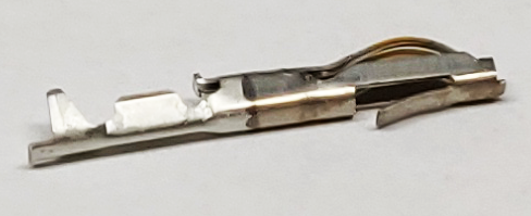
Mini Universal Mate'n'Lock Crimp Set
 |
|
|---|---|
| Insight PN | 770986-1 |
| Digikey PN | A25676-ND |
| TYCO PN | 770986-1 |
| Used In | Oil Pressure Sensor Harness |
| Construction | Brass/Tin |
| Wire Size | 22-26 AWG |
Inspecting Probes and Harness Leads
NOTE: All Insight Thermocouple Probes Are Grounded.
Not Recommended With Other Instruments Requiring Non Grounded Probes.
First, you have to have the right tools for the P2 connector.
Tyco AMP Crimping Tool P/N #601966-1 Military Spec #M22520/2-01
K13-1 Positioner P/N # 601966-5 Military Spec # M225202/2-08
Insertion / Extraction Tool P/N 91067-2
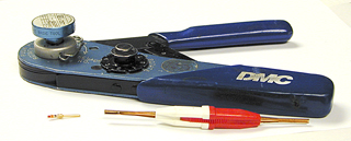
DMC crimper K13-1, with the insertion/extraction tool for gold pins: Connector Pin & Crimp Socket,
D-Sub Style Connector
Tyco Amp crimping tool; for Twin Leaf Pins/Mini Universal Mate’n Lock Set; Edge Style Connector
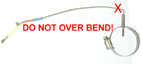
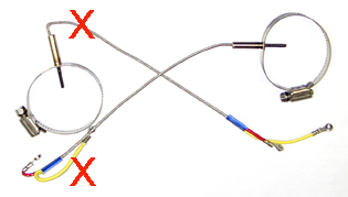
WARNING about installing probes
The minimum radius of bends in wire groups or bundles must not be less than 10 times the outside diameter of the largest wire or cable, except that at the terminal strips where wires break out at terminations or re-verse direction in a bundle. Where the wire is suitably supported, the radius may be 3 times the diameter of the wire or cable. Where it is not practical to install wiring or cables within the radius requirements, the bend should be en-closed in insulating tubing. The radius for thermocouple wire is 20 times the diameter.
Test Probe
The following tests are used to inspect the probes and harness leads. In most cases, the cause of missing EGT, TIT, or CHT readings can be attributed to a problem involving the probes or harness wiring.
- Disconnect probe from harness wiring. Measure the resistance of the probe between the two leads. Correct reading should be less than a couple of ohms.
- Measure the probe for correct grounding. Measure the resistance from one of the probe leads to the engine case. This reading should be less than 10 ohms.
- If measurements above are good, remove the probe. Connect a meter across the two probe leads. Heat the probe using a torch or lighter. The resistance should always be less than a couple of ohms.
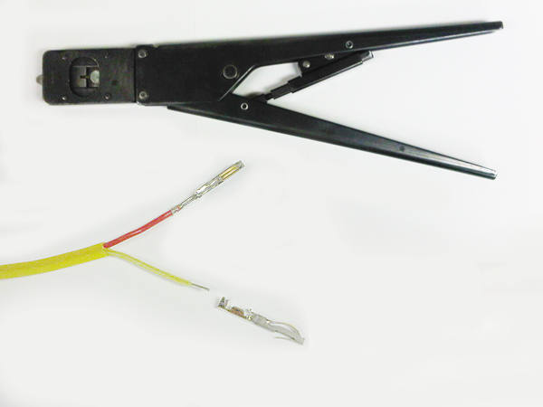
- Inspect the wiring harness for breaks and good crimps. Pull tautly on the crimp. It should not separate from the wire. Ensure that the wire is not pinched or broken. The wiring harness should not be bundled with ignition leads, P-leads, alternator wiring, or battery wiring.
- Inspect the pin connections at the instrument connector. Ensure that the pins make good contact with the circuit board. Tug on the wire. It should not pull free from the connector or pin.
- Harness leads can be difficult to troubleshoot. In most cases, it is ideal to replace the possible problematic wire with a new one. Please note that probe wiring cannot be spliced.
Test OAT Probe
How does the OAT probe operate
The Insight 1200-021 OAT probe is not a resistance type. It is a semi-conductor, output current proportional to absolute temperature type. The probe has a sensitivity of one micro-amp (1 uA) per Kelvin, and requires a minimum of four Volts (4V) to operate. For example at 0 Celsius (273 K) the probe draws 273 micro-Amps.
Testing OAT Probe -Test G Series for OAT
This tech note describes a simple test procedure
to verify normal operation of the OAT function on a
G-Series Graphic Engine Monitor (GEM). The test can be
performed on a bench, or in an aircraft if the
connectors at the back of the GEM are
accessible. - ![]() OAT
G Series Test
OAT
G Series Test
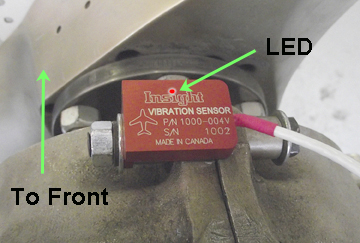
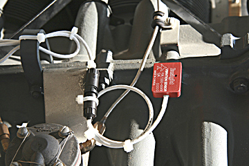
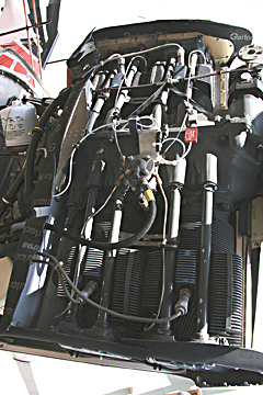
Location of Vibration Sensor
Tyco AMPLIMITE Two-Piece Spring Latch Information
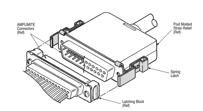
Click here for Tyco AMPLIMITE Two-Piece Spring Latch installation instructions.
This instruction sheet covers the installation and use of AMPLIMITE Two–Piece Spring Latches which are used with AMPLIMITE connectors.
Read these instructions carefully beore installing the spring latches.
 Probe
Diagnostic Screen
Probe
Diagnostic Screen
The Need for better Diagnostic Tools
Even the first GEM could detect an open probe and blank its indication. Over the years by helping owners and their mechanics trouble shoot instrument problems I developed a new understanding and sympathy for the challenge they faced.
Troubleshooting avionics is an expensive and time-consuming process. Often times the procedure requires access to the instrument connector for continuity measurements. This might take hours of instrument panel disassembly just to touch the connector. We needed something better, easier to use, less time consuming and therefore less expensive.
Why not have the instrument diagnose itself? Then you don’t have to disassemble the airplane or touch the wiring. This is not as easy as it might seem. Adding resistance measurement hardware for each and every probe wire would more than double the complexity of the measurement system. I considered this carefully during the development of the GEM-610 second-generation instrument. It would at least add a second PC board to the instrument and have even greater adverse impact on the GEMINI twin version. Even if we endured these problems to get the information, we had no practical way to display it on an orange bar display.
So I abandoned it then, but revisited again this time. The new color display was quite adept at displaying the information, eliminating that problem, but the data on resistance was still hard to obtain.
So this time I was able to invent a new way of measuring resistance. The simple idea worked beautifully without adverse impact on the design. It was so simple in fact even I was skeptical at first.
Without this simple breakthrough we’d still be diagnosing things the hard way.
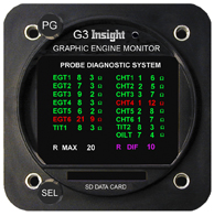
So, what does the diagnostic system do?
The probe diagnosis page indications are in
green for normal readings and red for readings
that fail the criteria set at the bottom of the
screen.
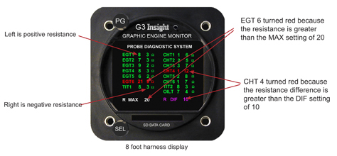
Each temperature probe consists of two wires, a
positive lead and a negative lead. The two
numbers next to each identifier show the
resistance in Ohms of each lead.
For example, the line EGT1 8 3 means the
positive lead of the EGT1 probe has 8 Ohms
resistance, and the negative lead has 3 Ohms
resistance.
When the probe is new, it will have relatively
low resistance.
As the probe ages, it’s resistance will slowly increase. Eventually, the probe will measure outside the pass/fail criteria you have set at the bottom of the screen, and change from green to red, indicating that the probe should be replaced before it fails and provides no temperature reading at all.
One other point to consider is that the
longer the wiring to the probes, the higher
the
resistance will be.
Every foot of EGT wire adds 1.7 Ohms/ft for the
+ lead and 0.8 Ohms/ft for the - lead. Every
foot of CHT wire adds 0.8 Ohms/ft for the + lead
and 1.2 Ohms/ft for the - lead.
A 24 ft harness will fail the criteria that an 8
ft harness will pass with. That is why we allow
the user to modify the pass/fail criteria on the
bottom of the screen.
The meaning of the
pass/fail criteria is as follows:
R MAX sets the maximum resistance (in Ohms) that
any single lead may have. If the R MAX is set to
20 Ohms per probe with either the positive or
negative leads measuring greater than 20 Ohms,
this
will be annunciated in RED, otherwise it is
displayed in GREEN.
R DIF sets the maximum resistance (in Ohms) that the positive lead may differ from the negative lead. If R DIF is set to 10 Ohms, the positive and negative leads need to measure within 10 Ohms of each other to be annunciated in GREEN, otherwise it will be RED.
![]()