Probe Screen
 The
Need for better Diagnostic Tools
Even the first GEM could detect an open probe and blank its indication. Over the years by helping owners and their mechanics trouble shoot instrument problems I developed a new understanding and sympathy for the challenge they faced.
Troubleshooting avionics is an expensive and time-consuming process. Often times the procedure requires access to the instrument connector for continuity measurements. This might take hours of instrument panel disassembly just to touch the connector. We needed something better, easier to use, less time consuming and therefore less expensive.
Why not have the instrument diagnose itself? Then you don’t have to disassemble the airplane or even touch the wiring. This is not as easy as it might seem. Adding resistance measurement hardware for each and every probe wire would more than double the complexity of the measurement system. I considered this carefully during the development of the GEM-610 second generation instrument. It would at least add a second PC board to the instrument and have even greater adverse impact on the GEMINI twin version. Even if we endured these problems to get the information we had no practical way to display it on an orange bar display.
So I abandoned it then, but revisited again this time. The new color display was certainly adept at displaying the information, eliminating that problem, but the resistance data was still hard to get.
So this time I was able to invent a new way of measuring resistance. The simple idea worked beautifully without adverse impact on the design. It was so simple in fact even I was skeptical at first.
Without this simple breakthrough we’d still be diagnosing things the hard way.
|
So what does the diagnostic system do?
The probe diagnosis page indications are in
green for normal readings and red for readings
that fail the criteria set at the bottom of the
screen.
Each temperature probe consists of two wires, a
positive lead and a negative lead. The two
numbers next to each identifier show the
resistance in Ohms of each lead.
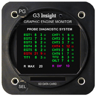
For example, the line EGT1 8 3 means the
positive lead of the EGT1 probe has 8 Ohms
resistance, and the negative lead has 3 Ohms
resistance.
When the probe is new, it will have relatively
low resistance. As the probe ages, it’s resistance will slowly go up. Eventually, the probe will measure outside the pas/fail criteria you set at the bottom of the screen, and change from green to red, indicating that the probe should be replaced before it fails and leaves you with no temperature reading at all.
One other point to consider is that the longer
the wiring to the probes, the higher its
resistance.
Every foot of EGT wire adds 1.7 Ohms/ft for the
+ lead and 0.8 Ohms/ft for the - lead. Every
foot of CHT wire adds 0.8 Ohms/ft for the + lead
and 1.2 Ohms/ft for the - lead.
A 24 ft harness will fail the criteria that an 8
ft harness will pass with. That is why we allow
the user to modify the pass/fail criteria on the
bottom of the screen.
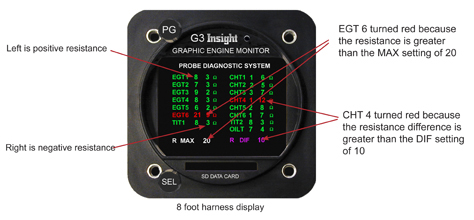
R MAX sets the maximum resistance (in Ohms) that
any single lead may have. If the R MAX is set to
20 Ohms a probe with either the positive or
negative leads measuring greater than 20 Ohms
will be annunciated in RED, otherwise its
displayed in GREEN. R DIF sets the maximum resistance (in Ohms) that the positive lead may differ from the negative lead. If R DIF is set to 10 Ohms, the positive and negative leads need to measure within 10 Ohms of each other to be annunciated in GREEN, otherwise its RED.
Proper setting on G1234 with 8, 10, 14 foot harness should be R MAX 20 R DIF 10 Proper setting on G1234 with 20, 24 foot harness should be R MAX 25 R DIF 15 Proper setting on G1234 with 30, 35 foot harness should be R MAX 30 R DIF 20 |

