News
 Choosing the right
engine monitor
"Click Right Here"
 Radio Ad.
Sound/SnF2017_InsightInstruments.mp3
SUN ‘n FUN Radio Broadcasts locally on 1510 AM & audio streams worldwide on www.LiveATC.net/snf.
WOW!! Many thanks to all the people who came to the Insight booth.
It was great to put a face to the many pilots and mechanics we talk to on the phone.
Air Venture pictures of 2016 -
Just wait to you read the story about this picture below!
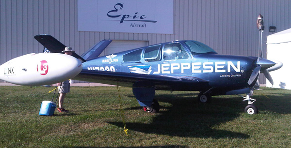
"Solo, around the world flight in a Beechcraft Bonanza" - Must Read
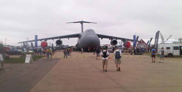
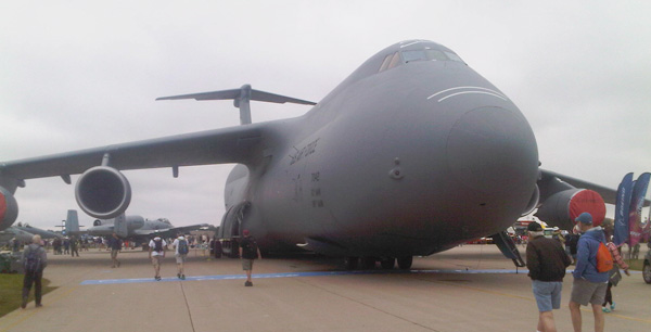
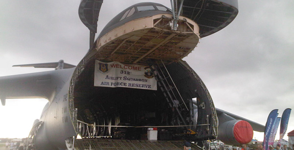
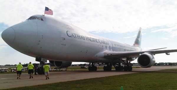
More pictures soon
Air Venture pictures of 2015 -
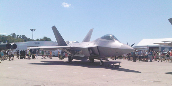
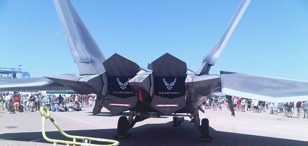
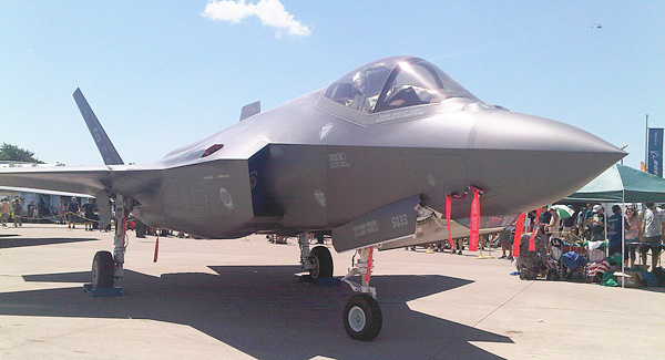
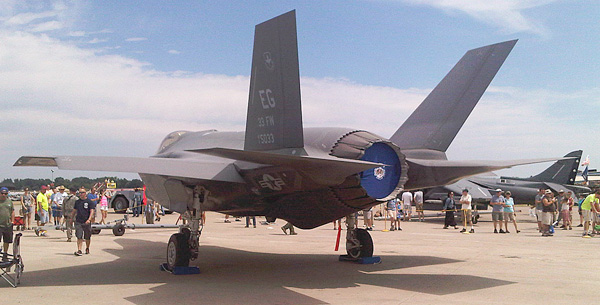


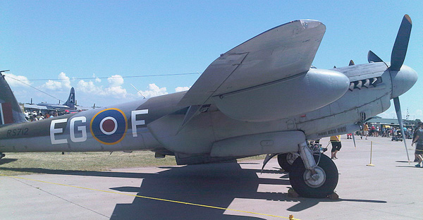
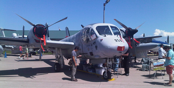
Did everyone see this -
Is this a Eurofighter_Typhoon_Single_Seater or a Fairey Gannet T2
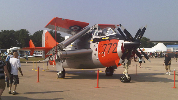

You have to check this out - http://theballybomber.com
3 new features for G3/G4: |
1 - Hard landing dynamic G-force data capture
G3/G4 have two new screens between Two Axis Turbulence and Takeoff G-force which display live G-force and a snapshot of the G-Force from last event (threshold exceeded).
The new transient G-force screen shows you the whole event the moment it happens.
You won’t miss a thing.
The event is also marked and stored in the log file for easy reference later.
2 -
Fahrenheit or Celsius
New G3, G4 single, or G4 twin engine monitors can now be shipped in Fahrenheit or Celsius.
If you have a G3, G4 single, or G4 twin and update to the latest version your temperature measurements will remain in Fahrenheit unless you configure your instrument for Celsius. So if you wish to keep using Fahrenheit do nothing further.
3 - G3/G4 data-logging capabilities extended
G3/G4 can now receive air data from a TAS-1000 Multi-Function Data Source.
• TAT (Total Air Temperature)
• IAS (Indicated Air Speed)
• TAS (True Air Speed)
• ALT (Pressure Altitude)
• WD (Wind Direction)
• WS (Wind Speed)
• HDG (Heading)
These new features are available at no charge to all current customers in the latest update and on all new G3 & G4 monitors.
Just download and update your instrument from our web site.
(G3 Software version 284 & G4 Single - Twin Software version 159)
This makes the G3/G4 to be the most affordable complete data logging system in aviation today.
Below is a must read
Shock
Cooling Myth Revisited
The myth of cylinder damage from rapid cooling has
largely faded from the scene but still comes up from
time to time. It is hard to trace the shock cooling
idea to it’s origin but it is easy tell where it
didn’t come from. Neither engine or airframe
manufactures have ever condoned it nor has the FAA.
Some engine or cylinder providers have mentioned it
to hide or explain away cylinder failures that might
be attributed to another cause like poor quality or
poor repair procedures. Some instrument manufactures
jumped on the band wagon and cheered shock cooling
into fame by make a warning feature in their
instrument. They did so without any scientific basis
for whether shock cooling existed or what cooling
rate would be safe and what rate would be dangerous.
Decades ago at the height of the myths popularity
Kas Thomas published a technical article that
exposed the lunacy of the idea and not too many
people took it seriously after that. Some others
conducted experiments to prove the shock cooling
myth but no one ever succeeded. One such experiment,
the most extreme that I am aware of, involved
heating a cylinder to the redline temperature and
then submerging it in acetone. Acetone normally used
as a solvent happens to have an extraordinary high
thermal conductivity. This would create a cooling
rate far beyond what could happen with air cooling.
Guess what? Even under these extreme conditions no
damage occurred. If cylinders could be damaged by
rapid air cooling wouldn’t cooling from rainfall be
a lot worse? If so wouldn’t the front cylinders take
a terrible beating from rain exposure while the rear
cylinders would be protected? Do the front cylinders
have a high failure rate compared to all the others?
(they don’t) If flying through rainfall caused
cylinder damage and catastrophic engine failures
would piston engine airplanes ever be permitted to
fly IFR? The more you think about it the more
preposterous the myth of shock cooling becomes.
Now you know why Insight has never produced an
instrument with a shock cooling feature and never
will. There is simply no scientific basis to do so.


The US patent office has granted the G series patent.
It is the most comprehensive engine monitoring patent ever granted.
All of the G series unique and revolutionary ideas
are protected for 20 years.
Meeting unprecedented demand
Sales growth of the new G series engine monitors has exceeded all of our forecasts and expectations. While our in house automated surface mount manufacturing facility builds a complete instrument in less than 2 minutes we have had to quadruple our technical staff just to keep up. We appreciate the patience of everyone that waited way too long for their instruments. Our phone lines are often tied up, if you have trouble getting through please try again in a few minutes. We do respond to all messages but doing it the same day as we have done in the past is increasingly difficult. When you do leave a message please tell us your time zone and acceptable hours for contact. Leave us alternative numbers like your cell phone if you wish to increase our ability to reach you. We’ll try our best to reach you.
We say goodbye to the backlog
Finally our single engine G series order back log is satisfied and from now on, we hope to ship all standard configurations promptly from stock.
The G4 twin is now shipping
We are now shipping G4 twin instruments fulfilling
our backlog as quickly as possible. The G4 twin is
built from the solid G3 & G4 single platform so it
should be trouble free from the very beginning.
High value products at low cost
To keep costs low we build everything in house. Machining, molding, probes, sensors, PC board assembly, - we do it all.
We couldn’t offer our lowest cost G1 instrument any other way. We love to hear our competitors complain our prices are too low.
A product that just gets better and better
Everyone has access to free software updates on the web. It takes only seconds to transform an older instrument to capability of a new one. Keep an eye on our update page to benefit from our constant software improvements. Updates are free.
We say goodbye to orange Plasma Displays forever
Plasma displays are a form of vacuum tube technology. In their heyday in the 60’s they started to appear in avionics in the 70’s. We first used them in the Graphic Engine Monitor in 1978 because you could get them custom made to your own design. At the time there were no other viable alternatives. But they failed from use and even faster from lack of use. Over the years their quality diminished while the price quadrupled. We were delighted to abandon plasma displays on the Strike Finder years ago.
Now we say goodbye to orange plasma displays forever. Our entire G series product line uses modern color LCD displays with long life LED backlights. Vacuum tube displays have no place in modern engine monitors.
Better fuel interface for dual instrument twins
The dual G4 configuration for twins is more popular than we expected. Current GPS’s won’t elegantly handle two separate fuel data streams. We have a little adapter to merge two independent fuel data sources to eliminate this limitation.
SUN‘n FUN was a huge success!
Insight would like to take this time to thank all
the great aviators that came to Lakeland Florida for
SUN'n FUN.
With the increased demand for our new G Series
monitors we had to get a double
booth this year and it’s a good thing we did.
We had a full page ad of show specials running in
SUN‘n FUN TODAY with radio spots during the air show
everyday.
Even did a live radio interview on SUN‘n FUN Radio
1510 AM (Now that was fun)
With all this great support for the most advanced graphic engine monitor in aviation today, Insight has expanded its workforce to keep up with demand and are looking for more.
All Insight products are all designed, prototyped,
manufactured, assembled and shipped from Insight.
Here at Insight we now have added a 3D printer for
research, development and prototyping.
What is 3D printing?
Fused Deposition Modeling (FDM) is an additive
manufacturing technology
commonly used for modeling, prototyping, and
production applications.
FDM works on an "additive" principle by laying down material in layers. A plastic filament or metal wire is unwound from a coil and supplies material to an extrusion nozzle which can turn the flow on and off. The nozzle is heated to melt the material and can be moved in both horizontal and vertical directions by a numerically controlled mechanism, directly controlled by a computer-aided manufacturing (CAM) software package.
The model or part is produced by extruding small beads of thermoplastic material to form layers as the material hardens immediately after extrusion from the nozzle.
Stepper motors or servo motors are typically employed to move the extrusion head.
The technology was developed by S. Scott Crump in the late 1980s and was commercialized in 1990.
3D printing is considered distinct from traditional machining techniques (subtractive processes) which mostly rely on the removal of material by methods such as cutting and drilling.
The technology is used in jewelry, footwear, industrial design, architecture, engineering and construction (AEC), automotive, aerospace, dental and medical industries, education, geographic information systems, civil engineering, and many other fields.
Want to see the type of 3D Printer Insight has - http://www.youtube.com/watch?v=i_5a4fMDLYk ![]()
"G Series – the only engine monitor that just keeps getting better and better"
